- 您现在的位置:买卖IC网 > Sheet目录886 > TMK063CK1R5DPGF (Taiyo Yuden)CAP CER 1.5PF 25V C0K 0201
�� �
�
�◆Soldering�
�?� Ceramic� chip� capacitors� are� susceptible� to� thermal� shock� when� exposed� to� rapid� or� concentrated� heating� or� rapid� cooling.�
�?� Therefore,� the� soldering� must� be� conducted� with� great� care� so� as� to� prevent� malfunction� of� the� components� due� to� excessive� thermal�
�shock.�
�?� Preheating� :� Capacitors� shall� be� preheated� sufficiently,� and� the� temperature� difference� between� the� capacitors� and� solder� shall� be� within�
�100� to� 130℃.�
�?� Cooling� :� The� temperature� difference� between� the� capacitors� and� cleaning� process� shall� not� be� greater� than� 100℃.�
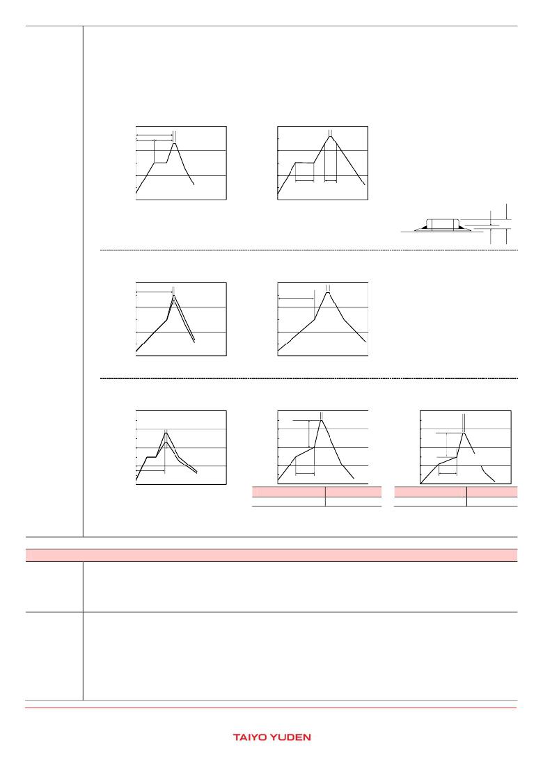
�[Reflow� soldering]�
�【Recommended� conditions� for� eutectic�
�soldering】�
�【Recommended� condition� for� Pb-free�
�soldering】�
�300�
�Preheating�
�60sec.� 60sec�
�230℃�
�Within� 10sec.�
�300�
�Peak�
�260℃� Max.�
�Within� 10sec.�
�200�
�Min.�
�Min.�
�Slow� cooling�
�200�
�Slow�
�cooling�
�100�
�100�
�Preheating150℃� Heating� above�
�60sec.� Min.�
�230℃�
�0�
�0�
�40sec.� Max.�
�Caution�
�①The� ideal� condition� is� to� have� solder� mass� (fillet� )controlled� to� 1/2� to� 1/3� of� the�
�thickness� of� a� capacitor.�
�②Because� excessive� dwell� times� can� adversely� affect� solderability,� soldering� duration� shall�
�be� kept� as� close� to� recommended� times� as� possible.�
�[Wave� soldering]�
�【Recommended� conditions� for� eutectic�
�【Recommended� condition� for� Pb-free�
�soldering】�
�soldering】�
�Solder�
�Capacitor�
�PC� board�
�1/2T~1/3T�
�T�
�300�
�200�
�Preheating�
�120sec.� Min.�
�230~250℃�
�Within� 3sec.�
�300�
�200�
�120sec.� Min.�
�Peak�
�260℃� Max.�
�Within� 10sec.�
�Slow� cooling�
�Preheating�
�Slow�
�cooling�
�100�
�0�
�100�
�0�
�150℃�
�Caution�
�①Wave� soldering� must� not� be� applied� to� capacitors� designated� as� for� reflow� soldering� only.�
�[Hand� soldering]�
�【Recommended� conditions� for� eutectic�
�soldering】�
�【Recommended� condition� for� Pb-free�
�soldering】�
�400�
�300�
�230~280℃�
�Within� 3sec.�
�400�
�300�
�Peak�
�350℃� Max.�
�Within� 3sec.�
�400�
�300�
�Peak�
�280℃� Max.�
�Within� 3sec.�
�⊿T�
�200�
�200�
�Slow� cooling�
�200�
�⊿T�
�Slow� cooling�
�100�
�Slow� cooling�
�100�
�Preheating�
�150℃� Min.�
�100�
�Preheating�
�150℃� Min.�
�Preheating�
�0�
�60sec.� Min.�
�0�
�60sec.� Min.�
�0�
�60sec.� Min.�
�⊿T�
�⊿T�
�316type� or� less�
�⊿T≦150℃�
�325type� or� more�
�⊿T≦130℃�
�Caution�
�①Use� a� 50W� soldering� iron� with� a� maximum� tip� diameter� of� 1.0� mm.�
�②The� soldering� iron� shall� not� directly� touch� capacitors.�
�5.� Cleaning�
�◆Cleaning� conditions�
�1.� When� PCBs� are� cleaned� after� capacitors� mounting,� please� select� the� appropriate� cleaning� solution� in� accordance� with� the� intended� use�
�Precautions�
�Technical�
�considerations�
�of� the� cleaning.� (e.g.� to� remove� soldering� flux� or� other� materials� from� the� production� process.)�
�2.� Cleaning� condition� shall� be� determined� after� it� is� verified� by� using� actual� cleaning� machine� that� the� cleaning� process� does� not� affect�
�capacitor's� characteristics.�
�1.� The� use� of� inappropriate� cleaning� solutions� can� cause� foreign� substances� such� as� flux� residue� to� adhere� to� capacitors� or� deteriorate�
�their� outer� coating,� resulting� in� a� degradation� of� the� capacitor's� electrical� properties� (especially� insulation� resistance).�
�2.� Inappropriate� cleaning� conditions(� insufficient� or� excessive� cleaning)� may� adversely� affect� the� performance� of� the� capacitors.�
�In� the� case� of� ultrasonic� cleaning,� too� much� power� output� can� cause� excessive� vibration� of� PCBs� which� may� lead� to� the�
�cracking� of� capacitors� or� the� soldered� portion,� or� decrease� the� terminal� electrodes'� strength.� Therefore,� the� following� conditions� shall�
�be� carefully� checked;�
�Ultrasonic� output� :� 20� W/?� or� less�
�Ultrasonic� frequency� :� 40� kHz� or� less�
�Ultrasonic� washing� period� :� 5� min.� or� less�
�?� This� catalog� contains� the� typical� specification� only� due� to� the� limitation� of� space.� When� you� consider� the� purchase� of� our� products,� please� check� our� specification.�
�For� details� of� each� product� (characteristics� graph,� reliability� information,� precautions� for� use,� and� so� on),� see� our� Web� site� (http://www.ty-top.com/)� .�
�c_mlcc_prec_e-E02R01�
�发布紧急采购,3分钟左右您将得到回复。
相关PDF资料
TO1608-102M
INDUCTOR 1000UH 70MA 1608 +-20%
TO3316-102M
INDUCTOR 1000UH 300MA 3316 +-20%
TPL1183427-722J-720N
COIL TRANSPONDER 7.2MH SMD
TS5022-102M
INDUCTOR 1000UH .55A SHLD 5022
TVX2A220MAD
CAP ALUM 22UF 100V 20% AXIAL
TWR-5/1000-12/210-D12A-C
CONV DC/DC TRI OUT 5,12,-12V
TWR-5/1500-12/250-D48A-C
CONV DC/DC TRI OUT 5,12,-12V
TWR-5/3000-15/500-D48A-C
CONV DC/DC TRI OUT 5,15,-15V
相关代理商/技术参数
TMK10024
制造商:TE Connectivity 功能描述: 制造商:TE Connectivity / Schrack Brand 功能描述:
TMK105 BJ103KV-F
制造商:TAIYO YUDEN 功能描述:Ceramic Multilayer Capacitor
TMK10524
制造商:TE Connectivity 功能描述: 制造商:TE Connectivity / Schrack Brand 功能描述:
TMK105ABJ474KV-F
功能描述:CAP CER 0.47UF 25V X5R 0402 制造商:taiyo yuden 系列:M 包装:剪切带(CT) 零件状态:在售 电容:0.47μF 容差:±10% 电压 - 额定:25V 温度系数:X5R 工作温度:-55°C ~ 85°C 特性:- 等级:- 应用:通用 安装类型:表面贴装,MLCC 封装/外壳:0402(1005 公制) 大小/尺寸:0.039" 长 x 0.020" 宽(1.00mm x 0.50mm) 高度 - 安装(最大值):- 厚度(最大值):0.022"(0.55mm) 引线间距:- 引线形式:- 标准包装:1
TMK105ABJ474KVHF
功能描述:0.47μF 25V 陶瓷电容器 X5R 0402(1005 公制) 0.039" 长 x 0.020" 宽(1.00mm x 0.50mm) 制造商:taiyo yuden 系列:M 包装:剪切带(CT) 零件状态:有效 电容:0.47μF 容差:±10% 电压 - 额定:25V 温度系数:X5R 安装类型:表面贴装,MLCC 工作温度:-55°C ~ 85°C 应用:汽车级 等级:AEC-Q200 封装/外壳:0402(1005 公制) 大小/尺寸:0.039" 长 x 0.020" 宽(1.00mm x 0.50mm) 高度 - 安装(最大值):- 厚度(最大值):0.024"(0.60mm) 引线间距:- 特性:- 引线形式:- 标准包装:1
TMK105AC6105KV-F
功能描述:1μF ±10% 25V 陶瓷电容器 X6S 0402(1005 公制) 制造商:taiyo yuden 系列:M 包装:剪切带(CT) 零件状态:在售 电容:1μF 容差:±10% 电压 - 额定:25V 温度系数:X6S 工作温度:-55°C ~ 105°C 特性:- 等级:- 应用:SMPS 过滤器 故障率:- 安装类型:表面贴装,MLCC 封装/外壳:0402(1005 公制) 大小/尺寸:0.039" 长 x 0.020" 宽(1.00mm x 0.50mm) 高度 - 安装(最大值):- 厚度(最大值):0.024"(0.60mm) 引线间距:- 引线形式:- 标准包装:1
TMK105AC6105MV-F
功能描述:1μF ±20% 25V 陶瓷电容器 X6S 0402(1005 公制) 制造商:taiyo yuden 系列:M 包装:剪切带(CT) 零件状态:在售 电容:1μF 容差:±20% 电压 - 额定:25V 温度系数:X6S 工作温度:-55°C ~ 105°C 特性:- 等级:- 应用:SMPS 过滤器 故障率:- 安装类型:表面贴装,MLCC 封装/外壳:0402(1005 公制) 大小/尺寸:0.039" 长 x 0.020" 宽(1.00mm x 0.50mm) 高度 - 安装(最大值):- 厚度(最大值):0.024"(0.60mm) 引线间距:- 引线形式:- 标准包装:1
TMK105B7103KV-F
功能描述:多层陶瓷电容器MLCC - SMD/SMT CAP MLCC 0402 25V X7R 0.01uF 10%
RoHS:否 制造商:American Technical Ceramics (ATC) 电容:10 pF 容差:1 % 电压额定值:250 V 温度系数/代码:C0G (NP0) 外壳代码 - in:0505 外壳代码 - mm:1414 工作温度范围:- 55 C to + 125 C 产品:Low ESR MLCCs 封装:Reel